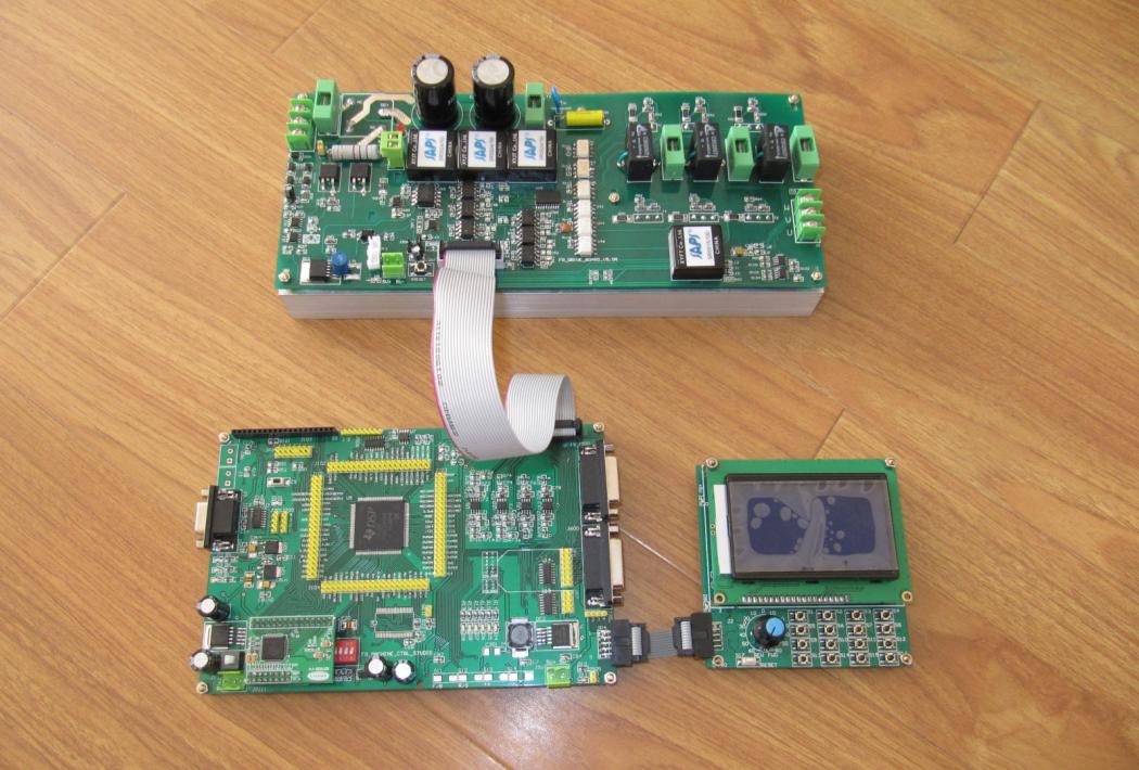

28335 control panel features
The main control chip of the control panel isTITheTMS320F2335, yes32Bit floating point high speed digital processor, maximum operating frequency150M.
Control panel peripherals:1RoadRS-232Interface.2RoadCAN2.0Interface.8Road expansionADInterface.1AEEPROM, the chip is24LC08. AllGPIOAll ports are led out to facilitate secondary development. Provides interfaces with driver board and display board for easy connection. Two differential encoder interfaces are provided. You can use the serial port A external boot program (use serial port A to burn hex Files without emulator ators); Dedicated external reset chip. Supporting our store power amplifier board can develop all types of motors. It can be used to develop three-phase six-leg two-level PWM rectifier and photovoltaic inverter.
Keyboard display panel features
The display board uses serial ports andDSPControl panel communication. Serial port baud rate is9600bps, no check bit, data bit8, stop bit1. Keyboard use4*4Matrix keyboard, using10Buttons, reserved for users6For self-development and use.
Display board use12864LCD to display relevant information, including: running or stopping status, forward or backward status, motor speed can be displayed (differential photoelectric encoder needs to be connected), set operating frequency can be displayed, DC bus voltage can be displayed.
Power amplifier board features
Motor power supply220VACInput, the power supply voltage deviation is required to be less than positive and negative10%; Or useDCDC power supply, power supply voltage is not greater48 V.
Maximum drive1500WMotor, the maximum peak current can reach25A.
Power amplifier board use5VDCThe power supply works. When working normally5VDCicc, idd1.0ALeft and Right.
Adopt4Independent power drive solution for eachIGBTReliable conduction and shutdown, completely eliminate the possible risks of single power from lifting power supply.
Use dedicatedIGBTDriver Chip and25A1200VTheIGBTTube.
Use Hall sensor to detect the output current waveform to completely isolate the low-voltage side from the high-voltage side.
DC side voltage sampling, isolated by linear optocoupler.
Six RoadPWMControl signal input, using high speed optocoupler to completely isolate the high voltage and low voltage sidePWMDrive signal to ensure that the driver board is not disturbed by high voltage.
PWMUpper and Lower Bridge arm straight-through circuit protection. When the upper and lower bridge arms of the same phasePWMWhen the pulse is straight, power amplifier board locks the fault, blocks all driving pulses, and displays them through the light emitting diode. When manual hand reset is required, the power amplifier board can be restarted.
PWMThe upper and lower bridge arms are directly protected by hardware. Both the input terminal and the three-phase output terminal are equipped with Fuse as overcurrent protection, which can also protect power amplifier board and load under the condition that the driving pulse has overcurrent and the protection circuit is not operated timely.
Equipped with voltage dependent resistor to prevent damage caused by DC bus overvoltage.
Equipped with power input indicator light, bus voltage indicator light, input pulse direct alarmLEDIndicator light, bus protection discharge indicator light.
IGBTThe connection with cooling fin should not only consider the heat dissipation problem, but also considerIGBTInsulation between cooling fin. In this power amplifier board, alumina ceramics are used to replace the traditional silica gel pad. Its thermal resistance is smaller than that of silica gel pad, and its insulation is more reliable. It will not cause the aging problem of insulation and heat dissipation performance as silica gel pad aging over time.
Power amplifier board is equipped with DC bus discharge circuit. When no access is available220ACWhen the power supply occurs, the bus starts to discharge, and the discharge indicator light is on at the same time. The main purpose of this circuit is to protect users from forgetting the high voltage of the bus after use and causing electric shock hazards.