SALE 19% OFF
Product description:
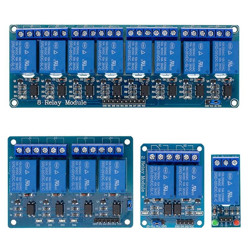
1 channel relay module
- Maximum load: AC 250V/10A, DC 30V/10A
- Trigger current: 5mA
- Working voltage: 5V
- Module size: 50 x 26 x 18.5mm (L x W x H)
- Four mounting bolts holes, diameter 3.1mm
- DC+: positive power supply (VCC)
- DC-: negative power supply (GND)
- IN: can be high or low level control relay
- NO: normally open relay interface
- COM: Common Interface Relays
- NC: normally closed relay interface
- 2 channel relay module
-
1 Dimensions: 50.5mm (length) * 38.5mm (W) * 18.5 (H)2 Weight:. 31g3.PCB Color: Black4 board four weeks with four screws holes, hole diameter 3.1mm, easy to install and fixed5 relay of high quality loose music relays SPDT. A common terminal, a normally open, one normally closed terminal6 optocoupler isolation, good anti-jamming7 low pull, high release. Energisation status indicator light, release status LED is off8.VCC of system power, JD_VCC relay power. You can plug in jumpersElectrical parameters:Supply voltage: 5VDC, 12VDCCurrent: more than 100mALoad: 250V 10A AC or 30V 10A DCWiring:VCC: positive power supply systemGND: System power negativeIN1 – IN2: relay control ports
-
4-channel relay output modules, relay output contacts 250A 10A. Input IN1, IN2, IN3, IN4, the signal line LOW effective. VCC, GND power input, can relay a separate power supply relay power input of JD-VCC.
Uses:
1, support all MCU control.
2, the industrial sector;
3, PLC control;
4, smart home control -
8 channel relay module
-
Features
Using high-current relay , AC250V 10A DC30V 10AContact some independent wiring , safe and reliableStandard interface , can be extended in a variety of development boardWith fixed screw holes for easy installationSuitable for a variety of platforms such as 51/AVR/AVR/ARMModule Description :1 , the module complies with international safety standards , the load control area and regional isolation tank ;2, using double-sided FR-4 circuit board design, high-end chip production process ;3, using loose music authentic relay control ;4, with the relay instructions , pull off, disconnect does not shine ;5, the signal input has a low signal , often beginning with a common terminal will be turned on ;6 , the relay can control the various devices and the load ;7 , 8 and 8 normally open normally closed contact ;8 , blue KF301 terminals to the control line is more convenient.9 , Module size : 138m * 56mm * 18.5mm ( L * W * H ) , Weight : 120g10 with 4 fixing bolt holes , hole 3.1mm, pitch 131mm * 49.5mm11 , finished by 100% functional testing and stability testingTwo module interface :1, VCC: 5V power supply connected to the positive2, GND: 5V power supply connected to the negative3, IN1-IN8: trigger signal , active lowRelay outputs : a 12- line interface, the interface can be directly connected to all leads , user-friendly1, NO1 – NO8: normally open relay interfaces , relay before the vacant after the pull shorted with COM2, COM1 – COM8 Relay Common Interface3, NC1 – NC8: normally closed relay interface relay shorted with COM ago , after the pull- vacantLow Level 5V solid state relay:Product description:
1. Omron 5V solid state relay 240V 2A, the output with a resistive fuse 240V 2A.2. size:1 way: 25 * 34 * 25 (long * wide * high)2 way: 55 * 33 * 25 (long * wide * high)4 way: 57 * 55 * 25 (long * wide * high)8 Way: 106 * 56 * 25 (L * W * H)3. input power: 5V DC (160MA)4. the input control signal voltage:High level module: (0-2.5V state low level relay ON)(3.3-5V state high level relay OFF)Low level module: (0-2.5V state low level relay OFF)(3.3-5V state high level relay ON)5. there are 2.54CM pin and blue KF301 terminal control line is more convenient.Input section:
DC +: Connect the power supply positive (according to the relay voltage)DC-: Connect the power supply negativeCH1: 1 relay module signal trigger terminal (low level trigger active)CH2: 2 relay module signal trigger terminal (low level trigger active)CH3: 2 relay module signal trigger terminal (low level trigger active)CH4: 2 relay module signal trigger terminal (low level trigger active)High and low meaning:
High-level trigger refers to the signal trigger side (IN) and the negative power supply has a positive voltage between the positive and the power supply is usually connected to the trigger side of a trigger, when the trigger side voltage or trigger to reach the trigger Voltage, the relay is pull.Low-level trigger refers to the voltage between the signal trigger terminal and the negative terminal of the power supply is OV, or the voltage of the trigger terminal is lower than the voltage of the positive terminal of the power supply. When the voltage is low enough to trigger, the relay is pulled in, The negative side of the power supply is connected to the trigger side of a trigger, so that the relay is pull.Electrical parameters:
Voltage Version Quiescent Current Operating Current Trigger Voltage Trigger Current1 channel 5V 0mA 12.5mA 0-2.5V 2mA2 5V 0mA 22.5mA 0-2.5V 2mA4 5V 0mA 48mA 0-2.5V 2mA4 5V 0mA 102mA 0-2.5V 2mAproduct manual:
1. Module power supply: the power must be DC, the voltage and the relay voltage to match2. Wiring method:When the trigger side of the signal trigger level, the relay will be connected, the device has electricity and workPrecautions:1. Module power supply: power must be DC, 5V power supply2. Module control terminal voltage: This module can only be used to control the AC current, can not control the DC current.


