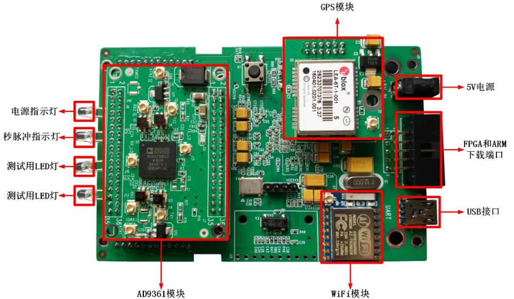

AD9361Software Radio Development BoardPhysical drawings are as follows:

SRF_AD9361_V2.0The motherboard includes supporting:
(1)4DebugLED;
(2) an ordinary person50MHZCrystal oscillator;
(3) oneGPSConstrained clock subsystem14bit DAC+VTCXO)
(4)SRF_AD9361_V2.0Modular
(5Timing typeUblox GPSModular
(6)Altera EP4CE55 FPGAIt can be customized;
(7)STM32F407ARMMaximum frequency168MHZFloating point arithmetic unit;
(8)USB 2The serial port module supports double serial ports, and the maximum speed of each serial port is9216000Baud/s
(9)WiFiIt can be configured as router or common user interface card;
(11)4KB EEPROMStorage user configuration;
(12Manual reset button (reset)FPGA,FPGAresetARM,ARMresetSRF_AD9361_V2.0ModularARMYesSRF_AD9361_V2.0Notify when module configuration is completeFPGA);
(10OptionalUSB 3High speed channel;
The development board principle diagram is as follows:

AD9361Schematic diagram of software radio development board
We also provide full version of the boxed version, which is easy for users to develop. The boxed version is made up ofUSB 3Power supply, without external power supply. The photo of the boxed version is as follows:

ARMandFPGAThe download line is connected to the master via an adapter board. Implemented on the master and can be downloaded through an interfaceARMIt can also be downloadedFPGAPurpose. Specific connection method, as shown in the following figure.

Measured, not less than60MHzSatisfyAD9361Design specification requirements.
We are on the RF input board of the development boardRX1The results are obtained by inputting signals of different power respectively:
The signal generator sends the signal and the receiving device is used after collectionMatlabDraw graphs in frequency and time domains.
Signal strength:-30dBmCarrier frequency:921MHzSignal bandwidth: single tone


Signal strength:-30dBmCarrier frequency:2.4GHzSignal bandwidth: single tone


Signal strength:-50dBmCarrier frequency:2.4GHzSignal bandwidth: single tone


Signal strength:-70dBmCarrier frequency:2.4GHzSignal bandwidth: single tone


Signal strength:-90dBmCarrier frequency:2.4GHzSignal bandwidth: single tone


Signal strength:-95dBmCarrier frequency:2.4GHzSignal bandwidth: single tone


Signal strength:-110dBmCarrier frequency:2.4GHzSignal bandwidth: single tone


Broadband signal reception test: the signal generator generates the signal and compares it with the spectrum analyzer and the device to be tested.
Signal strength:-30dBmCarrier frequency:100MHzSignal bandwidth:8MHz


Signal strength:-30dBmCarrier frequency:921MHzSignal bandwidth:8MHz


Signal strength:-30dBmCarrier frequency:2.4GHzSignal bandwidth:8MHz


Signal strength:-30dBmCarrier frequency:2.4GHzSignal bandwidth:16MHz


Signal strength:-30dBmCarrier frequency:2.4GHzSignal bandwidth:20MHz


Signal strength:-30dBmCarrier frequency:2.4GHzSignal bandwidth:28MHz


To test the transmit power, we designed a Beidou type pseudo satellite signal with a center frequency of1585MHZBandwidth is4MHZ. Send a picture of the signal below:

Frequency of transmitted signal center1.585GHZ(in order to avoid interference)GPSBeidou (Beidou)

Transmit signal bandwidth4MHZ(imitate Beidou pseudo code bandwidth)
The signal power of the spectrometer is17dBmAs shown in the following figure.

AD9361The RF board is as follows:

Among them,J6andJ7The interface between the module’s power supply and the digital circuit consists of two18*2The pin, pin spacing2mmElicitAD9361All digital interfaces. Power supply for5VDirect.
Module RF signal input and output throughIPEXInterface and external connections, the following table for eachIPEXInterface description.
| IPEXInterface | input/output | numerical value | Function description |
| J3 | output | send aisle2 | |
| J11 | input | Maximum input power2.5dBm | Receive channel2 |
| J12 | output | J3after19dBAfter the gain is output toJ12. | |
| J13 | input | Maximum input power2.5dBm | Receive channel1 |
| J14 | output | send aisle1 | |
| J15 | output | J14after19dBGain after outputJ15 | |
| J16 | output | AD9361Receive local oscillator output. | |
| J17 | output | AD9361launchLocal oscillator output. |
Detailed information:
yinzitu.com/SRF_AD9361_V2.pdf